Introduction
Mechanics
Electronics
Software
Conclusions

EE/CS118 Final Project 2002
Mechanics
|
Solid edge mockup of the robot 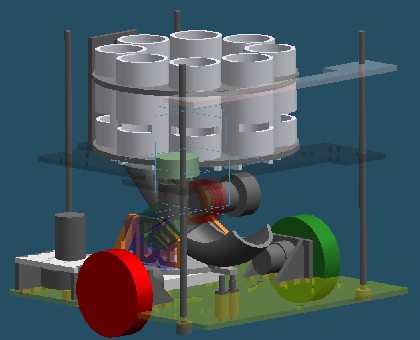
|
The Assaulted, in all its glory after having been assaulted. 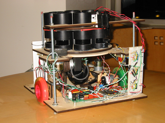
|
In designing the mechanical systems of our robot, we tried as hard as possible to stick to the philosophy of keeping things as simple as possible. All of our subsystems, including those responsible for driving, aiming, and loading, were designed to eliminate as many variables as possible. By doing so, we theorized that we would be able to shoot baskets accurately and with high reproducibility. The robot subsystems are detailed below.
Pitcher
|
Solid edge mockup of the pitching subsystem 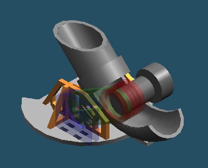
|
The actual pitcher. 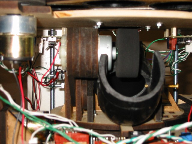
|
This was our way of delivering the “perfect stroke” from behind the arc. It consisted of three components: 1) a J-pipe, 2) a pitching wheel, and 3) a rotating turret.
J-pipe
The J-pipe coupled the loader with the pitching wheel. The long decline before contact with the pitching wheel ensures that all the balls loaded follow roughly the same path. The pitching wheel contacts the ball at approximately the bottom of the J, accelerating the ball up the J to get a nice parabolic arc tangent to the ball’s separation from the end of the J.
Pitching Wheel
To drive our pitching wheel we used a high speed low torque motor from Jameco. The pitching wheel was a 2” foam wheel from the San Antonio hobby shop. Since the shaft was a little bit smaller than the bore of the wheel, we used Aerotubing to couple the shaft with the wheel. This gave it a very nice and tight fit and held the wheel tight to the shaft.
We mounted the motor into a housing of 4 MDF rings glued onto a slotted adjustable arm. The MDF rings provided vertical stiffness so the motor would not rotate clockwise when dangling, or counterclockwise when it contacted a yellow nerf ball. The arm had 2 degrees of freedom since it was slotted and the binding pieces were also slotted. We could rotate the arm to any reasonable theta, and extend (or shorten) the arm to a variety of radii.
Rotating Turret
This component was designed so that we could hard code the aiming through mechanical stops. We made a small protrusion on the tip of our circular turret to stick out and hit screws or solenoids sticking out from the platform beneath. To calibrate left and right we cut slits in the platform so we could slide the screws more left or right. To create center stops we used 2 solenoids: if we were coming from the right, the left solenoid would pop up to create a stop; if we were coming from the left, the right solenoid would pop up to create the stop. This way we were always centered correctly even through our turret protrusion had finite length. |
|
Rotating Column
|
Solid edge mockup of the rotating column 
|
The actual column. 
|
We wanted a method for loading the balls into our pitching mechanism fast enough so that we could shoot our entire capacity in the time allotted, but also slow enough so that we would not be feeding balls into the pitcher before the pitcher was properly aimed. This was known as the Kishan dilemma, and was the basis for our rotating column design.
The Column
We were pretty much set on a rotating column design from the onset because we wanted to drop each ball vertically to avoid friction between balls, and between ball and loader. The best geometry for this seemed to be 8 circularly arranged pipe segments, since we could stack balls up in each column and vertically drop each ball. We wanted our column to rotate and the lazy susan we had to mount underneath was square, so using 8 pipes was perfect for this since the square opening in the middle of this pipe configuration exactly resembled the dimensions of our lazy susan. We put one sheet of MDF on top and one on the bottom to increase the structural integrity of the column without increasing the weight very much. The top piece held on with rubber band engineering to make sure it was removable so we could get to the lazy susan screws underneath in case anything came unscrewed (which it did). Each column was made of 2" ABS pipe carefully bandsawed and sanded down to a precise 5".
Dispensing
Supplying the balls one at a time was our next task. We went through a few iterations in this step:
Plan A: Two Solenoids
Initially we thought the most efficient way to do this was to empty one column of balls at a time since we could probably do this faster than we could rotate the column. The idea was that we could use 2 solenoids in a gating configuration for each column: the first solenoid would block the bottom ball while the second blocked the ball above it (and all the balls above that). When the first solenoid popped open, the bottom ball would be allowed through while the second solenoid held the remaining column of balls. The bottom solenoid would pop close, and the second solenoid would open to let the column shift one balls length down. The top solenoid would close and this whole process would repeat until we were out of balls. This was a good idea at first since we believed that we could make our columns very high and hold 5 or 6 balls before having to rotate. We even managed to optimize this design so that instead of using 2 solenoids per pipe (16 solenoids!), we only needed 2 solenoids as long as we cut slits in the pipe for the solenoids and rotated each pipe into the solenoids.
Plan B: One Solenoid
After designing the pitcher and base, however, we realized we could only optimize column height to hold 3 or 4 balls max. We also realized that the solenoids we bought were fat and bulky and only had a push/pull range of 0.25”, so placing these solenoids correctly added another degree of complexity. Plus the solenoids were $8 a piece, so we really didn’t want to break the seal. Realizing this, we tried to design for a one solenoid setup where we replaced the top solenoid with a ledge just to block the ball. If we had a ledge, we would have to rotate the column past the obstruction before the balls above the ledge would fall. So we could either rotate forward a little bit and rotate back to empty the same column before moving on, or we could continue rotating in the same direction and drop the first ball from the next column and so on. Now the Kishan dilemma stated that if we loaded a ball into the pitcher before it finished aiming we would waste a ball on a bad shot. Because the pitcher was mounted on a lazy susan, this meant that we had to load the pitcher slower than the turret spun. The famous Kishan theorem stated if the column rotated at a fixed speed, as long as that speed is slower than the turret’s speed, we will always be done aiming before the next ball is loaded. This was key.
Plan C: No Solenoids
Having continuous rotation meant that there was no reason to gate the bottom ball any more, so now we needed no solenoids. By the time the next column arrived, it would be time for the next ball to be loaded into the pitcher. A consequence of continuous rotation was that we only had to deal with static friction once: when we begin column rotation. At this point we could power up our motor at full speed for a fraction of a second to overcome static friction, and then PWM our drive speed back down to a nice “slow” ~3 sec / pipe.
The Ledge
The ledge was quite a piece of engineering in itself. Because we eliminated all solenoids from our loader, we still needed some way to ensure that only one ball would be dispensed to the pitcher at a time. We decided that a simple ledge mechanism would be easy to design and calibrate, and provide us with all of the functionality that we required. As the ledge would be interfacing between two of the yellow nerf balls, we needed to design it so that it would smoothly roll the top nerf ball over itself, while letting the bottom ball drop out. If it was too skinny or sharp, the balls would get caught and stall our motor. So we used a two screw design. We cut two slits vertically into MDF so we could dynamically adjust ledge height, and then bolted the screws to the MDF piece. In addition, to insure the MDF piece stayed perpendicular to the platform while remaining removable, we mounted it with 2 screws to a small brass L-bracket to the platform. The screws provided a nice thickness to the ledge, but the threads were a threat to balls catching and holding onto the screws. To fix this problem, we wrapped the screws in electrical tape, smoothing out the threads and providing a nice ledge for the top ball to roll over. In order to allow the screws to protrude into the pipes, we needed slots cut out of the sides of the pipes. In an adventurous move, one of our intrepid team members spent a morning in the machine shop with the milling machine, which we thought would give us the best and most precise way of cutting the slots out of the pipe without damaging the rest of the cylinder. Using a three-jawed chuck to fix each piece, and cutting with a .5" end-mill, only 24 passes at 50 thousandths per pass were needed to cut a precise rectangular slot halfway through the pipe, which had an outer diameter of 2.4". This process was repeated for each of the eight columns. In a surprising turn of events, our complete loading mechanism worked exactly as planned the first time we tried it, a telling tribute to the intelligent designs from our mechanical engineering team. |
|
Lower Platform
We designed the base of our robot as basically a square to take full advantage of the 13”x13” space allotted to us. Because the back end was flat, we were able to back up into the wall and straighten our robot out.
Drivetrain
We chose to drive our wheels directly since historically the high torque motors we bought have been able to withstand the stress of these robots’ weight on their bearings. To keep this platform as close to the ground as possible, we created motor mounts above the platform. This allowed us to place the platform within an inch from the floor.
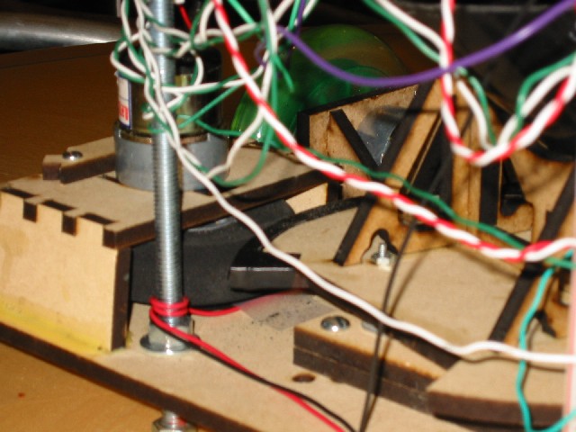
Turret Motor
In the spirit of conserving space, we mounted our turret driver upside down so the motor’s body would not need to be below the platform. Space between the lower and upper platforms was ample. Since this motor mounting also needed to be adjustable, we slotted the screwholes for the motor. Once it was properly placed, we placed a backing piece of MDF to prevent the motor from sliding backwards. |
|
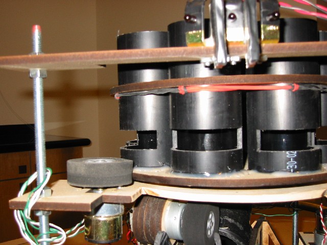
Upper Platform
|
This platform was designed to hold the rotating column and the high torque motor necessary to drive the column. The column was mounted with a 3” lazy susan, with a hole underneath the ledge to let out Nerf ball. The hole is noncircular and extends towards the center of the rotating column so that when balls are released into the J-pipe, they will not bounce and get stuck between the J-pipe and upper platform. This platform is also Y-shaped instead of square (like the lower platform) to avoid being shot by the pitcher. Our clearance between the front of the platform and the ball’s projectile is minimized so that we can lower the upper platform as much as possible and increase the height of our column pipes (total ball capacity). Underneath the platform was the ideal place to mount our 3 H-bridges since we could minimize wiring from these locations. The upper platform is attached to the lower platform via 4 12” screws. Since we only had 2 wheels, we extended these screws through the bottom platform so that these screws also served as feet for our robot to prevent it from tipping over. In addition, we could calibrate these feet lengths so that the robot would be correctly weighted on both drive motors to back up straight. |
|