Introduction
Mechanics
Electronics
Software
Conclusions

EE/CS118 Final Project 2002
Electronics
IR Beacon Sensors
We originally contemplated using two IR Beacon sensors, both oriented in such a way that they would be facing the right and left baskets when the robot was facing the center basket. When intially turning to face center, this design would have forced us to constantly look at the output of both sensors and trigger an event when they both output the same value. However, we felt that there were too many variables associated with what value our sensors would output, and that we could not trust them to behave as we would have liked when turning to face center. For that reason, we decided that it would be best to add a third sensor that faced the center basket. This way we would only have to wait for the center beacon sensor to output a high value while turning to face center.
Return to topPhototransistors: To capture the light signal transmitted by the IR beacons, we used LTR-3208E NPN phototransistors in a sinking configuration. The collector voltage was fixed at 5 Volts and the emitter voltage at 2.5 Volts by tying the emitter output to the V- input of a LM324 operation amplifier (where the V+ input was tied to 2.5 Volts). Fixing VCE to 2.5 Volts allowed us to achieve a 2.5 Volts output swing, which was amplified to a 5 Volt swing in later stages. The following is a diagram of the circuit used to obtain the IR becaon signal:
![]()
Filtering: Our initial design decision was to use a single pole high pass active filter in order to attenuate the signal from the ambient room light and retain only the signal from the IR beacons. We decided that it was best to use a cutoff frequency of 1 kHz, giving us plenty of room for error (since the room lights emitted light at a frequency of 300 Hz). Using an example of a scalable high pass filter which we found through an online reference, we designed the filter shown below:
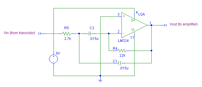
Unfortunately this design did not work for a number of reasons. First, it did not do a good enough job of attenuating the ambient room light signal. Even when the IR Beacons were not on, the circuits would still output an appreciable signal. While there was still enough difference between this output signal and the output signal we obtained when the IR Beacons were turned on, we feared that this would no longer be true if the ambient light were to get brighter. Second, we needed an additional amplification stage in order to obtain output values that could be read by the analog to digital converter on the MC-11 board. We decided to change our initial filter design to a 2 pole high pass Chebyshev filter with a gain of 2. Using the equations provided in The Art of Electronics we designed the aforementioned filter, with a cutoff frequency of 1.1 kHz:
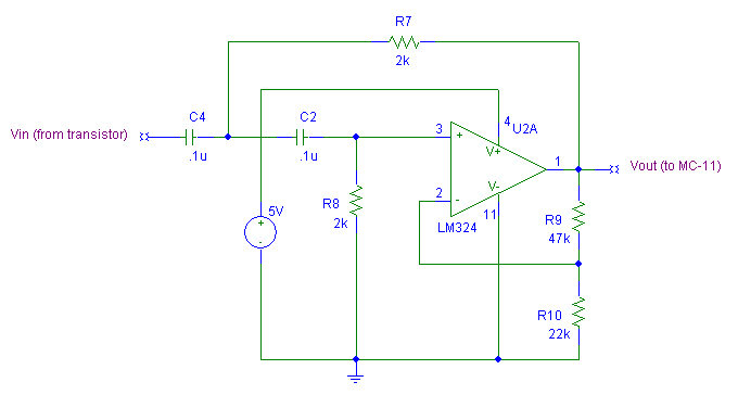
This design worked much better and we no longer obtained any sort of output signal without turning on the IR Beacons. Furthermore, we did not need to cascade a third stage of amplification; we were able to do all of the necessary amplification along with the filtering.
Return to topWe mounted our three sensors on L-brackets in such a way that each sensor was exactly in line with one of the three baskets. Because our robot was designed to stay in one place and shoot, it was highly important that we correctly found the center beacon during our initial stage of turning (ie. that it did not decide that it had found the center either before or after the center phototransistor was aimed exactly at the center IR Beacon). For us, this problem became harder than it was for others because our sensors behaved in the following manner:
- If the phototransistors were not aimed within less than 5 degrees of separation from the IR Beacons, our sensors would output a low voltage (0 Volts).
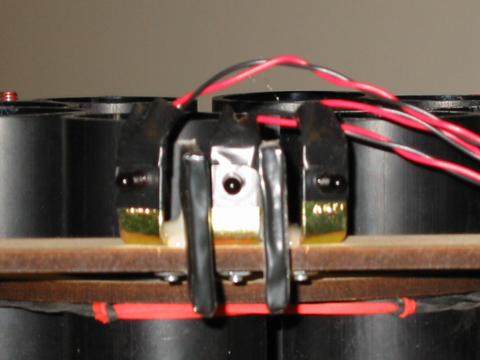
- If the phototransistors were aimed within less than 5 degrees of separation from the IR Beacons, our sensors would output a high voltage (5 Volts).
- Our sensors would not output any voltage in between the high and low rails.
Because of this behavior, while initially turning we could only rely upon the value of our center sensor (since when the robot faced center with only the center beacon on, only the center sensor would output a non-zero value), but our center sensor would trigger high once it was within 5 degrees of separation from the center beacon. For this reason we had to place blinders on either side of the center sensor so that it would only trigger high when it was exactly in line with the center beacon. We constructed the blinders from foamcore, wrapped in electrical tape. Once we had found the exact alignment for our blinders (after several test runs) we hot glued them in place so we would never have to worry about adjusting them again. The following image shows our final sensor arrangement: