Group Member
|
|
|
|
|
|
Youhao Jing yjing@cs.stanford.edu |
|
|
|
Qing-cheng Lu qclu@stanford.edu |
|
|
|
Xiao-zheng Ye yxz@stanford.edu |
|
Table of content
1. Introduction.
1.1.
Overview
1.2 Problem statement.
1.3 Motivation.
2. Design & Implementation.
2.1
General Design
2.2
Time Diagram.
2.3
Gateway.
2.3.1.
External interface design
2.3.2. External interface implementation.
2.3.3. Kernel-userspace interprocess communication(IPC)
2.3.4. TDM transceiver
2.4 Circuit Switch
2.5 Control Signaling
module.
2.6 TDM connection
2.7 Important design
considerations.
3. Implementation Stages.
4. Completed implementation
5. Future work.
6. Task list.
7. Reference.
1. Introduction.
1.1 Overview:
The goal of this project is to simplify the core
of the network in such a way that it can be implemented using optical switches,
while still providing simple, but hard QoS guarantees.
1.2 Problem statement.
A TCP Switch is a switch/router that intercepts TCP connection establishments and creates a pseudo-switched circuit to another TCP switch close to the destination end-host. During the creation of the pseudo-switched circuit, resources (mainly peak bandwidth) are allocated at the TCP Switches that the circuit traverses in the core of the network. The circuit creation, resource allocation and scheduling mechanisms are very simple, and they can designed to be implemented in optical switches, which are very fast, but they have little buffering capabilities or logic.
1.3 Motivation:
The goal of this project is to simulate the circuit switch network by packet switch mechanism. The goodness of doing so includes:
We will implement it on Linux box. In order to show the effect, we will simulate a Virtual Circuit switch on normal ethernet cards.Simplify the tcp network so that it can be implemented using existing telecommunication equipment, like optical switch. Improve the performance of the network by reducing routing time in the intermediate hops. Make the connection robust by using time out mechanism and fixed allocated bandwidth. Fully utilization of the network bandwidth, provide hard QOS service. Improve kernel programming experience.
2 Design & Implementation.
2.1 General Design - Divide and Conquer
There are two type of devices in our project. First is the devices
across the network
boundary between TCP circuit switch system and outside TCP network
. We call
these devices GATEWAY. Second is the devices inside of the
TCP circuit switch system . We
can just call them CIRCUIT SWITCH.
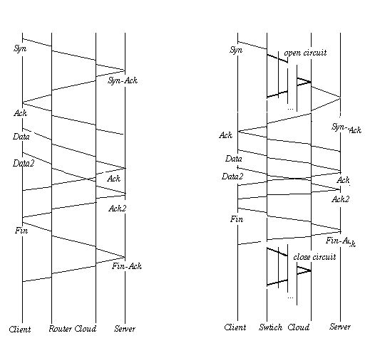
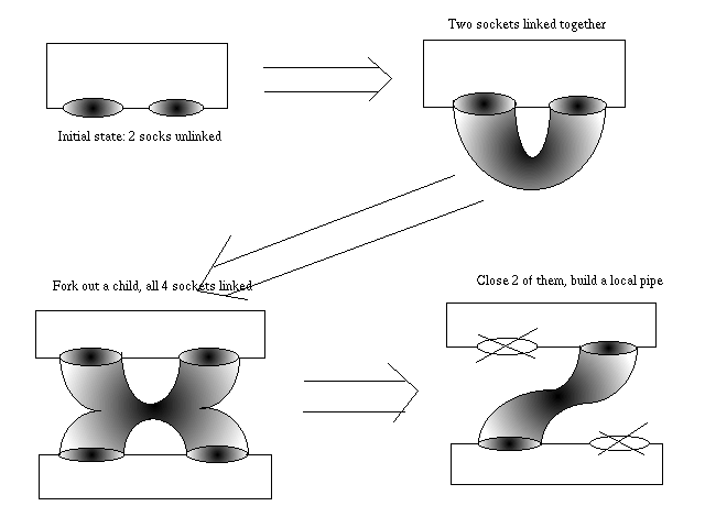
2.2 Time Diagram
Figure 2.2

2.3 Gateway
The gateway interface will make TCP circuit switch transparent to
outside packet switch world. Enable them work exactly the same as the normal
TCP connection. We can list functions of such a gateway:
1.Receive TCP packet from outside
2. Bandwidth management
3.Cut normal TCP packet into TDM slots
4. Send and receive TDM packet with a circuit switch
5. Reassemble TDM slots into TCP packet
6. Send TCP packet to outside
To achieve these goals, we will further divide a gateway module into two ends. One is to transfer data with outside TCP network, this module will implement above feature 1,6. The other is to deal with circuit switch, including above feature 2, 3, 4. We can call the first part as External Interface(appearing as Packet switch interface), the second part as CONTROL module.
The gateway block diagram is shown in the following figure: (blocks in the first line is a normal TCP stack, the two blocks attached to the first line is External Interface, other blocks consist a TDM Module and a Control Signaling Module)
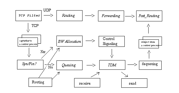
The gateway itself should be designed as following:
Theoretically, a TCP interface is very simple. The function here is just to capture the incoming and re-inject outgoing tcp traffic. But since we are implementing the system on a linux box, the best solution is to get the whole solution working inside of the kernel. Otherwise, we have to do context switch between kernel space and user space. Most importantly, such context switch has to be done for every packet. That should be a considerable amount of time limiting our interface's throughput.
Because such context switch may leads to more cache miss, especially
running on a typical PC with very limited cache system.
We can easily to calculate how often a context switch will happen
for a certain throughput:
For a 10 Mega bit per second throughput. Assumming average size of packet is 500 byte (source 1 ), that means every 0.4ms, there is a context switch. Each context switch penalty can reach up to 26,300 cycles (resource 3), that is 0.05ms for a 500 MHz processor. Takes approximately 10% of the run time resource. The minimal TCP packet size is 40 bytes. If we get all packets like such size, we can conclude here that such context switch may take nearly all the CPU resources. So, we have to apply some buffering mechanism inside of the interface.
Of course our goal of the whole project is not to reach the best output. But we show that a best solution for tcp interface design maybe a pure kernel implementation, or a pure user space one. Otherwise we may have to sacrifice some throughput. The designed throughput of our interfaces is at least 1.040 MBAs, based on a kernel user hybrid solution, which will discuss later.
2.3.2 External interface implementation:
We will implement our project on a linux 2.4 kernel. We have following
two functions part:
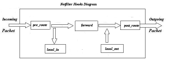
2.3.3 Kernel-userspace interprocess communication(IPC):
There are four ways to implement Kernel User space IPC in Linux,
character device, /proc/ file system, shared memory, and
netlink. We think character device has its special advantage:
2.3.4 TDM module:
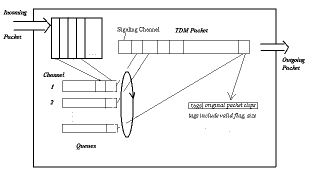
The implementation of the gateway control module is done
by using several parallel running processes which handle different tasks.
As shown in the following graph:
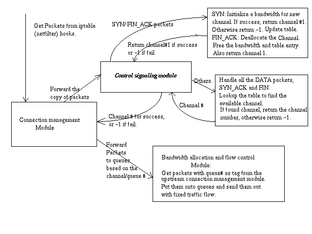
All the mapping information between src/dst ipaddr, TCP port#, VCI and queue# are stored in this table. Once this module get packets from its upstream--- connection management module, it will distinguish whether it's control packets or not. Control packet means the packet is used to control the setup or tear down of a certain channel, including SYN and FIN_ACK. (The reason to use FIN_ACK instead of FIN as control packet is that the channel can only be torn down after the FIN_ACK is sent back.) All other kinds of packets including DATA, SYN_ACK and FIN.
int child_pid; /* pid of child*/
/* The local pipe used to communicate with the ip-table hook*/
int localpipe;
/* The local socket used to do communication
* between the left part of the module and
* the right part of the module.
*/
int localpipead;
/* The last time this control module send packet to the circuit network
*/
struct timeval last_send;
/* The flag to show whether the control loop should continue*/
int control_loop_not_running;
/* The buffers used to hold the SPacks before they can be assembled into
* an ordinary big packet.
*/
char buffer[QUEUE_NUMBER*NET_CARD_NUMBER][4096];
int bufferpos[QUEUE_NUMBER*NET_CARD_NUMBER];
} ctr_module;
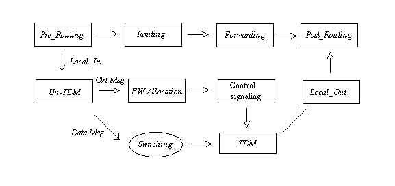
When switch receives the connection request it will try to determine which host is the destination, figureout which port it will go to, and allocate a bandwidth for it. Then it will generate a new control message, which is sent to the next hop, waiting for acknowledgment from next hop. If it is the destination or get acknowledgment from the next hop, it will ACK the previous hop that the channel has been setup successfully.
The block diagram of circuit switches is as following:
2.5 Control Signaling Module:
Control signaling module implements a Switch-to-Switch Protocol
(SSRP) for virtual connection
routing and TCP call setup signaling.
As described in earlier sections, TCP switch operates in two modes:
gateway mode and switch mode.
In each mode, TDM module consults with its local TDM time slot routing
table in order to switch
TDM data grams. The routing table in each TCP switch has the following
format:
| TCP flow ID | IP SA | IP DA | TCP Source Port | TCP Destination Port | Ingress TCP Switch ID | Incoming TDM timeslot | Egress TCP Switch ID | Outgoing TDM timeslot |
| 1 | 10.1.1.1 | 15.1.1.1 | 80 | 1108 | 10 | 2 | 11 | 3 |
| ...... | ...... | ...... | ...... | ...... | ...... | ...... | ...... | |
| 9 | 172.16.1.1 | 192.168.1.1 | 5555 | 1766 | 10 | 3 | 11 | 2 |
Table 2.5-1 Local Routing Table Format in TCP Switch
Note: Here we assume each TCP switch only have one ingress and egress interface.
Control signaling module implements a Switch-to-Swtich Protocol (SSRP)
to derive and maintain
above routing table in each TCP switch. A typical use of SSRP
in a TCP switched network is
illustrated in Figure 2.5-1. Figure 2.5-2 shows a Finite State Machine
(FSM) SSRP uses to discover
neighbor TCP switches and exchange routing information among the
neighbors.

Figure 2.5-1 Typical use of SSRP in a TCP switch networks
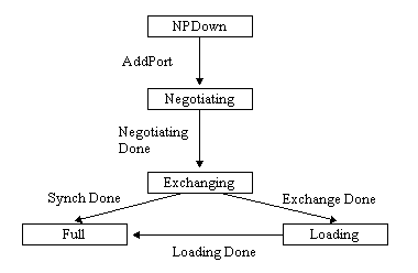
Figure 2.5-2 SSRP neighbor discovery/exchange Finite State Machine
SSRP is also responsible for dynamic TCP call setup throughout the
TCP switched network.
Consider a TCP switch-based network, as shown in Figure 1-1, Host
CPE1 originates a TCP call to
the host CPE2. Among the TCP gateways and switches, SSRP is used
to handle required call
admission control (CAC) signaling.
The SSRP call setup sequence is illustrated in Figure 2.2 .
SSRP Protocol Data gram Unit (PDU) Format
The SSRP uses UDP as its transport protocol. For the sake of simplicity,
TDM datagram time slot
one is used as common signaling channel for carrying SSRP PDU.
The SSRP Header Format
Each message has a fixed size header. The layout of the header is shown below:
+-+-+-+-+-+-+-+-+-+-+-+-+-+-+-+-+-+-+-+-+-+-+-+-+-+-+-+-+-+-+-+-+
|
|
+
+
|
|
+
+
|
Reserved
|
+
+
|
|
+-+-+-+-+-+-+-+-+-+-+-+-+-+-+-+-+-+-+-+-+-+-+-+-+-+-+-+-+-+-+-+-+
|
Length
| Type |
+-+-+-+-+-+-+-+-+-+-+-+-+-+-+-+-+-+-+-+-+-+-+-+-+
Figure 2.5-3 SSRP Header Format
Reserved:
This 12-octet field currently is not used.
Length:
Two-octet long integer indicates the total length of the message.
Type:
One-octet unsigned integer. The following type codes are defined:
1 Hello
2 Update
With the current size of TDM time slot being 128 bytes, each PDU carries three SSRP messages.
The SSRP Hello message has the following format:
1 Byte 1 Byte 1 byte
+-+-+-+-+-+-+-+-+-+-+-+-+-+-+-+-+-+-+-+
| Switch ID | Type | Hop count
|
+-+-+-+-+-+-+-+-+-+-+-+-+-+-+-+-+-+-+-+
| Switch ID | Type | Hop count
|
+-+-+-+-+-+-+-+-+-+-+-+-+-+-+-+-+-+-+-+
| Switch ID | Type | Hop count
|
+-+-+-+-+-+-+-+-+-+-+-+-+-+-+-+-+-+-+-+
| Optional Parameters
|
|
|
+-+-+-+-+-+-+-+-+-+-+-+-+-+-+-+-+-+-+-+
Figure 2.5-4 SSRP Hello Message Format
Switch ID:
1-octet integer denotes the identification number of the switch or gateway.
Type:
1-octet integer indicates the function type: gateway or switch
Hop count:
1-octet integer indicates the distance of specified gateway or switch
from current switch. For hop
count of zero, it indicates the current switch.
The SSRP Update message takes following format:
40 Byte
1 byte
+-+-+-+-+-+-+-+-+-+-+-+-+-+-+-+-+-+-+-+-+-+-+-+-+-+-+
| SYN/FIN
| Conn ID |S/F|T/O|
+-+-+-+-+-+-+-+-+-+-+-+-+-+-+-+-+-+-+-+-+-+-+-+-+-+-+
| SYN/FIN
| Conn ID |S/F|T/O|
+-+-+-+-+-+-+-+-+-+-+-+-+-+-+-+-+-+-+-+-+-+-+-+-+-+-+
| SYN/FIN
| Conn ID |S/F|T/O|
+-+-+-+-+-+-+-+-+-+-+-+-+-+-+-+-+-+-+-+-+-+-+-+-+-+-+
Figure 2.5-5 SSRP Update Message Format
In each update message, one TCP SYN (for call setup) or TCP FIN packet
(for call tear down) is
copied to the next hop, together with 6 bit connection identification
number, one status bit indicating
whether bandwidth reservation is successful or failed, and one status
bit for notifying next hop
whether or not time-out.
Summary of Operation
Upon the startup of a TCP switch, SSRP enters into neighbor
discovery and exchange FSM. They
exchange SRRP hello messages, and build up a network topology, and
consense on the role of each
switch.
When a host send TCP SYN to a gateway, that gateway starts the call
setup signaling sequence
with SRRP update message sent to the next hop. Each switch along
the path participate the same
setup process until a successful virtual circuit is setup for this
TCP flow. Meantime, upon the
bandwidth allocation in each hop, the TDM switching mapping is populated
into the local routing
table.
Upon receiving TCP FIN packet, adjacent gateway starts the call tear
down sequence with
SRRP update message. Each hop along the path frees up the bandwidth
and clears up the entry for
that connection in the local routing table.
Note:
The current design of SSRP only provides required functions for this
particular implementation. It
doesn't support incremental update mechanism and hierarchy group.
No timers are supported.
2.6 TDM Connection
Between every switches, we will setup one TDM connection, it will utilize all the assumed existing bandwidth. On every ethernet connection, we assume the total bandwidth can use is 1.0 M bit per second. For ethernet, the largest packet is 1.5k bytes, the packet size we will use is 1280 bytes, plus a 20 bytes header for control message, that's 1300 bytes. Every 10 ms, such a packet will be put on link to send out. We get the following equation:
We will divide each 1280 byte packet into 10 slots, 128 bytes each. Among this 128 bytes, 1 byte is a valid flag, marking if the slot is empty, 1 byte is the size information, for reassembling data in slots back to original TCP packet.
2.7 Some important design considerations.
1). Q: Why we choose netfilter and implement most part of our modules
in the userspace?
A: Recompile and reinstall kernel
of linux box is extremely tedious work. So direct implementing our project
in the kernel level is definitely unacceptable since every small change
in the kernel level can cause the crash of the whole system. So by using
netfilter, we can get the real-time information of the network without
disturbing the ordinary running of the whole machine, and since most the
modules are done in user space, every time we want to modify it, we only
need to recompile the userspace space program instead of killing the whole
machine. Another consideration of using userspace module is the easy way
of implementation itself. Since in the kernel level, many useful system
calls or library functions are not available according to the top down
hierarchical architecture. All those useful features can be easily accessed
in userspace.
At
the same time, except in the two end gateways, all the packets are transmitted
in the userspace alone the intermediate hops. So there is no need for us
to involve with the kernel process and it can improve our system stability.
2) Q: Why use UDP as the way to communicate in the circuit
cloud between gateways.
A: Since we have ensure the bandwidth
allocation in the two gateways, so once it's done, we assume there is no
packets to be lost in the intermediate hops since this channel and only
this channel will try to use the fixed bandwidth. And it's stable as long
as the physical link in the intermediate hops are robust. UDP is much easy
and fast since there is no need for it to wait for ACK for each packet.
3) Q: Why we choose a certain channel--- channel #1(which is
mapped to queue #1) to do the control packets transmission?
A: By this way, there is no need
for the intermediate hops to process the ordinary packets, since all the
control packets which needs ip-header lookup and table update have already
been put in Channel #1, all the ordinary packets can be just directly forwarded
to the next hop according the mapping table. So we can reduce the overhead
of the packets processing in the intermediate hops and reduce the round-trip
time. At the same time, since the control packet (SYN and FIN_ACK are both
40 bytes long, so we can put more than one control packets in the channel
#1.) Although we should allocate a specific bandwidth to handle the control
channel (In our implementation, 10 channels totally, 10% for control packets.),
we can still think it's a good design. In the real-time network traffic,
most network connection has pretty short of medium length life-time(for
example, http connection need a SYN, FIN with 2-3 data transmission session
between them, so about 20% of the network traffic will be the control packets.)
And since we can handle more than one control packets each time, one channel
should be enough and still not waste of channel resource.
4) Q: How do you prevent the unexpected connection failure
due the end?
A: We implement a timeout mechanism on
the channel, if one channel is idle for a certain time, (double round-trip
time) then we suppose the channel is terminated without FIN and the channel
slot will be free for future use.
5) Q: How to deal with the unexpected packet loss in the intermediate
circuit cloud.
A: We will attached a sequence number to each
UDP TDM packet. After sending out each UDP pakect, sender will wait a UDP
packet coming back with the same sequence number. Otherwise, it will re-send
the packet until it gets the correct answer.
3. Completed Implementation.
Our completed implementation as the first stage is:
2) The gateway connection module and kernel module was tested with
the real-time telnet/netscape traffic. Capture the outgoing tcp packets,
pass to connection module running in the userspace and re-inject back to
the network card after the processing.
4. Future work.
For future implementation, it is supposed to do finer tuning the performance and add features, the features to be added in can be:
* We will add classified services.
Since we can support different kinds of services in one switching
module and they should have different bandwidth requirements and priority
levels. We can implement the classified services based on their priority
levels by using priority tag. Then when those services enter the module,
we will allocate the bandwidth to them according to their priority levels.
(For example, SSH session and Netscape Browser session enter the module
at the same time, we should consider SSH session when there is a lack of
bandwidth.).
As in the first stage, we only implement the so called dummy single
link between two linux switching module. In another word, our circuit switch
is just several direct links between the correspondent ports between two
linux modules. While in the second stages, we should take care of the multi-sender
and multi-receiver cases, so we need to build the mapping tables stated
above.
Evaluate the performance of the simulated circuit switch network
by comparing it to the standard packet switch network. Since there is no
buffering and routing delay in the simulated circuit switch cloud, all
the transmission delay is coming from the buffering and processing delay
in the communication/switch linux boxes and the constant "transmission
delay" in the simulated circuit switch network cloud. So we can compare
it with the delay of the standard packet switch network whose delay comes
from the delay in all routing points.
5. Submitted Result.
The deliverable result of this project to simulate the circuit switch
system by packet switching.
6. Task list.
Xiao-zheng Ye:
Project design.
Connection management module(control.c, control.h).
Debugging and testing.
Qingcheng Lu:
Project design
Linux kernel module.(tshook.h, tshook.c)
Debugging and testing.
Youhao Jing:
Project design
Control signaling module.
7. Reference :
A tcp packet format can also be found in the TCP protocol document.
(RFC 793)
Netfilter programming, writing a module for netfilter
reference 1: http://staff.washington.edu/dittrich/misc/ddos/stream.txt
reference 2: http://www.ece.cmu.edu/~ee742/proj_s98/combs/
reference 3: http://www.eecs.harvard.edu/cs245/papers/Shieyuan.html